
Tim Mikkelsen's Arduino Projects
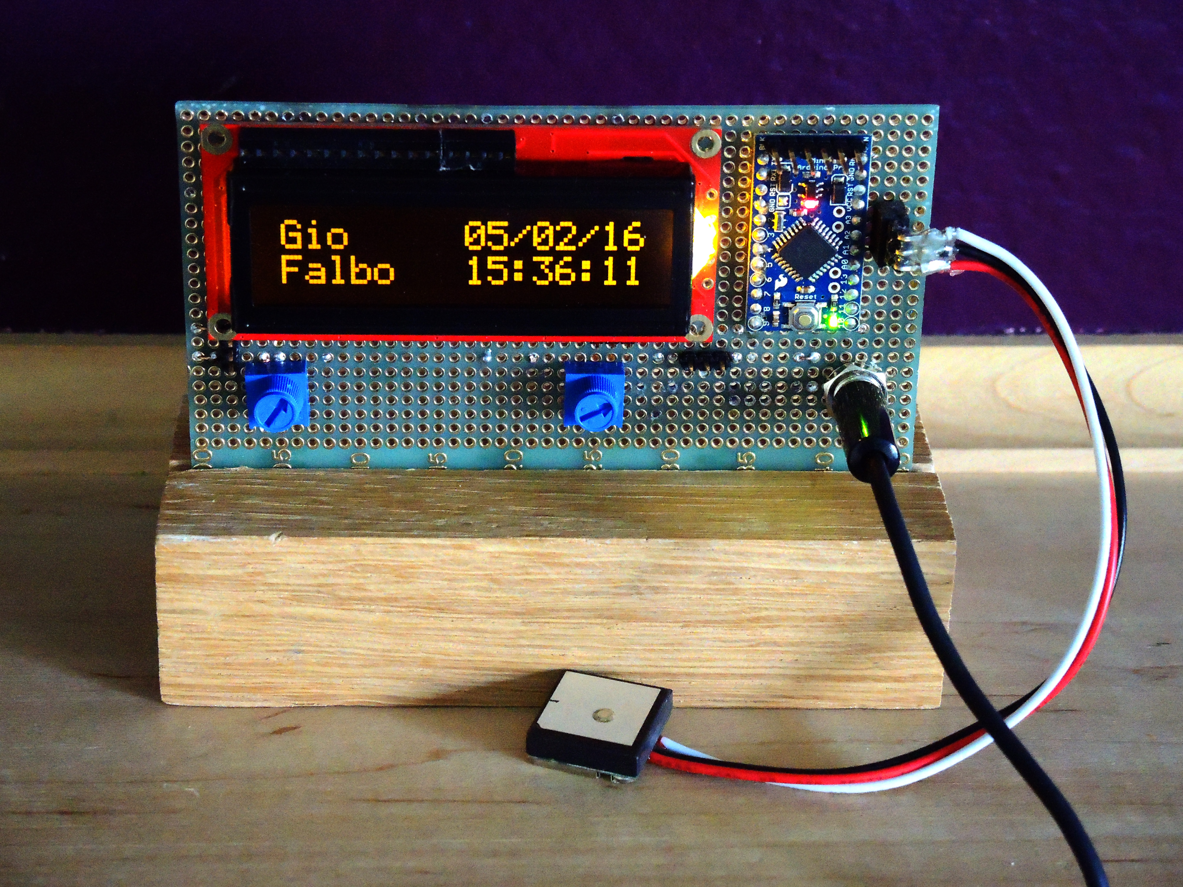
2016/04 Arduino LCD / GPS Clock
Description:
I had built a simple 7 segment night-light for my grandson, Gio, quite a while ago. I wired it up to spell out his name with 8 display segments - just a power supply, LED 7 segment displays, and resistors. I wanted to do something a bit better and thought a clock would be nice. In thinking about it, an Arduino would work really well. I didn't want to have to worry about setting or adjusting the time. The two obvious choices were to use a WWV decoder or connect via WiFi. Both would work but I felt they had issues. In looking around, I saw an inexpensive GPS receiver and felt that was the best way to go.
I did some prototypes and this worked out well.
In the code, there are tests that check the date and put up different messages on the top line of the display (family birthdays, holidays, etc.) These are only for fixed dates.
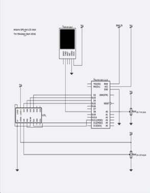
Hardware:
- Sparkfun DEV-11114 - an Arduino Pro Mini 8Mhz/3.3V (or a regular Arduino Sparkfun DEV-12757)
- Sparkfun DEV-09873 - FTDI Basic Breakout (to program the Pro Mini if used)
- Sparkfun LCD-00791 - a Basic 16x2 LCD display - HD44780 chipset
- Sparkfun GPS-13470 - a GPS Receiver - GP-20U7
- Sparkfun COM-09806 - two 10k trimpots
- 6v 200ma wall power supply
Total parts cost: Approximately $60
A few comments:
1. The GPS receiver wires were very fragile and I destroyed 2 in the process.
2. The first code used the regular serial library in the Arduino and it was dropping parts of the message. I needed to go to the SmartSerial library. This worked much better. (Setting the smartdelay parameter was very critical.)
3. Decoding the GPS messages was sort of goofy. I had used some code I found but in looking I found the TinyGPS++ library by Mikal Hart wihich is great. (You can get latitude, longitude, and altitude if you want it.)
4. Adjusting for time zone was 'interesting'. I found some code from Jinseok Jeon that helped with this which also dealt with daylight savings time.
5. I had originally built the design with 5 DIP switches to set time zone (1 sign bit and 4 bits for the zone). This was okay but required the switches and 5 pull up resistors. Looking at the Arduino, I had a bunch of unused analog inputs. I replaced the switches with a 10k trimpot and added some code to set the timezone by reading the voltage and scaling it. This replaced the switch components with a single trimpot.